Translate this page into:
Biomechanics of Extra-alveolar Mini-Implant Use in the Infrazygomatic Crest Area for Asymmetrical Correction of Class II Subdivision Malocclusion
This article was originally published by Wolters Kluwer and was migrated to Scientific Scholar after the change of Publisher.
Abstract
Asymmetric malocclusion has always represented a challenge to orthodontists, with different dental, skeletal, or dentoskeletal factors being probable causes for the condition. It is a key to distinguish between dental and skeletal asymmetry before determining a predictable force system for corrective treatment. The use of mini-implants (MIs) to address anchorage needs in modern orthodontic practice has become an important tool for orthodontists. They have been widely used for anchorage reinforcement purposes and placed in the dentoalveolar region, especially between tooth roots. However, placement sites other than root areas allow more versatility of orthodontic movement since tooth roots do not interfere in tooth displacement. The objective of the present study is to present a clinical case of asymmetric malocclusion (Class II division 1 subdivision), in which a MI placed in the infrazygomatic crest area was used for correction of the maxillary asymmetry by means of unilateral distalization. Biomechanics of unilateral molar distalization combined with skeletal anchorage has allowed predictable outcomes to be achieved with minimal need for patient’s compliance and minor side effects.
Keywords
Orthodontic miniscrews
mini-implants
Class II malocclusion

Introduction
Asymmetric malocclusion represents a challenge to orthodontists, particularly that affecting facial esthetics. The etiology of some cases of asymmetry might comprise dental factors, whereas other cases might be caused by primarily skeletal factors. There is yet a third group known as dentoskeletal asymmetry.[1] Dentofacial asymmetries are joined together in one or more variations in the same patient. In other words, the condition might comprise a dental issue associated with a skeletal one, thus characterizing a dentoskeletal asymmetry [Diagram 1].[1]
| Asymmetric malocclusion classification | ||
|---|---|---|
| Dental | Skeletal | Dentoskeletal |
| Maxillary/mandibular dentoalveolar implications or both. Face is usually symmetric | Maxillary/mandibular skeletal and facial implications or both | Maxillary/mandibular dentoalveolar and skeletal implications or both. Potential for facial symmetry implications |
Overall, dental asymmetries are the most prevalent in the dental office. They are caused by abnormal tooth eruption, premature loss of deciduous or permanent teeth, tooth crowding, among other factors. That type of asymmetry is rarely associated with facial deformities.[2] Patients with dental asymmetry usually have Angle’s Class I sagittal molar relationship on one side and Class II on the other side, which is associated either with midline deviation or the sagittal facial plane.[3] This malocclusion is also known as Class II subdivision and can be found in 50% of Class II patients.[4] In addition, it is one of the most prevalent asymmetric dental malocclusions shared by the orthodontic community.
The authors of a study on asymmetry[5] found an asymmetric molar relationship in 25% of cases of a given orthodontic population. Rates were higher than 2.5 mm. A different study assessing asymmetric molar relationship revealed 30% of young adolescents with no history of orthodontic treatment presented with asymmetry, whereas 22% of orthodontic cases were seen as asymmetric.[6] Asymmetry with midline deviation is a common clinical condition found in 46% of orthodontic patients and 21% of untreated young adolescents.[6] Furthermore, it has been evinced that 62% of midline discrepancy cases affected the lower midline, 39% affected the upper midline, 18% resulted from mandibular displacement, and 6% resulted from skeletal issues.
Once asymmetry has been diagnosed, it is key to distinguish between dental, skeletal, or dentoskeletal. Thus, it is the orthodontist’s responsibility to assess the cause of asymmetric malocclusion.[2] To properly diagnose and quantify the asymmetry, the following resources might be used: clinical facial assessment; cephalograms in oblique (45°) view or anteroposterior view (AP); submental vertex radiograph; as well as computed tomographic scans.[7] One of the most powerful tools used to diagnose asymmetry is clinical examination performed directly on the patient/ occlusion. The best means to develop one’s clinical facial assessment expertise is thorough and continuous direct evaluation carried out with photographs in frontal view.[8] Frontal facial assessment allows overall evaluation not only of patient’s facial symmetry but also of dental midline relationships with the facial axis.
In addition to the aforementioned diagnostic resources, asymmetry assessment has been highlighted in terms of providing a sharp view of orthodontic conditions by means of a new diagnostic tool. To this end, a given spatial orientation, including three rotational axes combined with the following well-known and renown planes, is used: AP, vertical, and transverse.[9] The previously mentioned axes are known as pitch, roll, and yaw.
The literature[7] has evinced that the major etiological factor behind Class II malocclusion subdivision is a defective (shorter) mandible on the Class II side (61%). The second clinical condition most commonly found in Class II subdivision cases is a maxillary permanent first molar mesially placed, which increases in 20% the cases of molar relationship discrepancy.[7] Thus, carrying out a thorough midline assessment is of paramount importance to identify deviation and, therefore, come up with an adequate treatment plan aimed at causing facial midlines to coincide by the end of orthodontic treatment.
In cases of Class II subdivision with upper midline discrepancy, should patients present with misally placed maxillary molars, the most common treatment of choice aimed at Class II correction could certainly be unilateral premolar extraction on the Class II side or unilateral distalization of first molars.[2,4,10-12] Several appliances, whether fixed or removable, have been recommended for distalization of maxillary molars. It is obvious that whether to use one appliance rather than the other is a decision that depends on a number of factors, including patient’s compliance. The use of mini-implants (MIs) for molar distalization in modern orthodontic practice has become an important tool for orthodontists. However, MIs have often been placed in the dentoalveolar region, especially between tooth roots, thus restricting tooth movement distally in cases requiring correction. Mini-screw placement sites other than root areas, as it is the case of the infrazygomatic crest (IZC), have been advocated in the literature, as they allow more versatility of orthodontic movement since high screws prevent tooth roots from interfering in tooth displacement.[13-18]
The objective of the present study is to present a clinical case of asymmetric malocclusion (adult female patient with Class II division 1 subdivision), in which a MI placed in the IZC area was used for correction of maxillary asymmetry by means of distalization and maxillary rotation.
Clinical
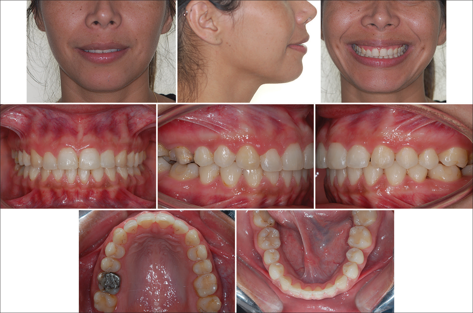
A 26-year and 9-month-old female patient sought orthodontic treatment with a chief complaint of “crooked” anterior bite and mandibular diastemata, both of which led to unpleasant esthetics. Figure 1 illustrate the case at treatment onset.
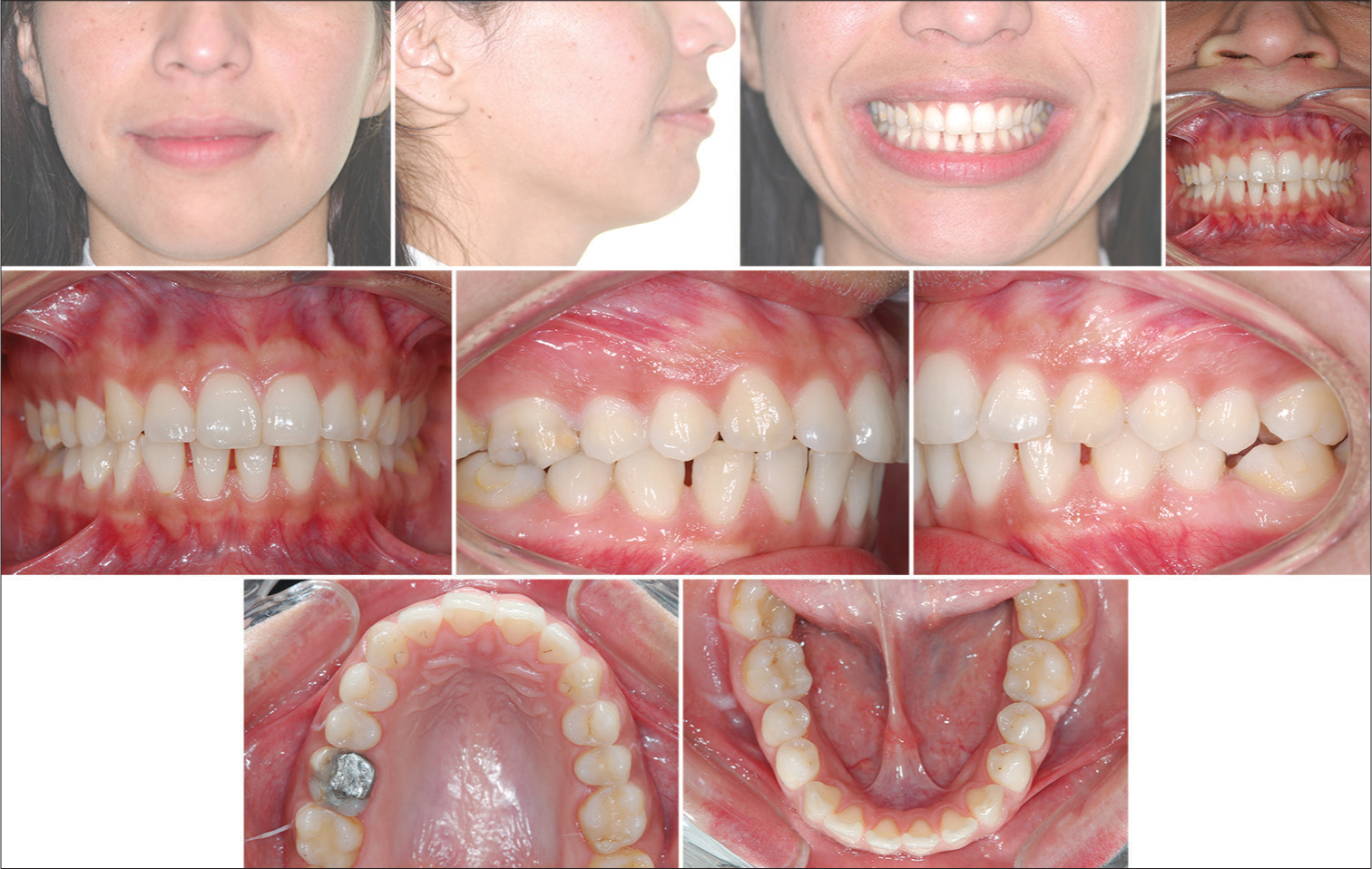
- 26-year and 9-month-old female patient initial photographs
List of problems
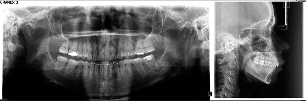
The patient presented with mesofacial pattern, symmetry, and passive lip seal. Profile assessment revealed a convex profile with clear mandibular deficiency, in addition to mild maxillary protraction and narrow nasolabial angle. Smile assessment revealed straight smile arc and 100% maxillary incisors exposure. The sagittal relationship between the maxilla and the mandible evinced Class II unilateral molar relationship, with the right side presenting complete Class II, while the left side presented Class I relationship. Canine on the right side presented complete Class II, while the left side presented Class I relationship. Overbite and overjet were completely normal. There was upper dental midline deviation equal to 3 mm to the left relative to the median sagittal plane. Lower dental midline was aligned. Maxillary crowding was minimal (1 mm), whereas mandibular crowding had mild 5-mm diastemata. Panoramic radiograph revealed all erupted teeth were present but mandibular first molars and left maxillary first molar [Figure 2]. Cephalometric analysis (cephalogram in lateral view) revealed Class II maxillomandibular relationship with maxillary protraction, well-positioned mandible, and vertical growth pattern [Table 1 and Figure 2]. Maxillary incisors were well positioned at the basal bone. Mandibular incisors were prominent and proclined at the basal bone. As regards soft-tissue facial profile, both upper and lower lips were proclined.
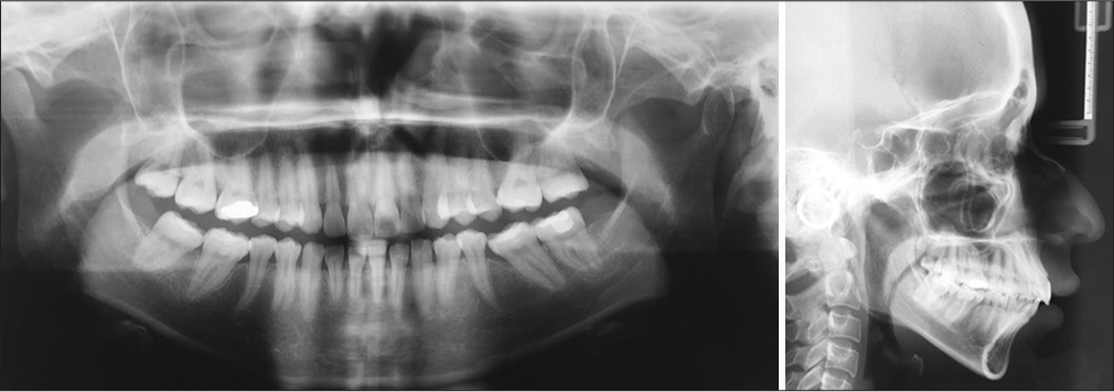
- Panoramic radiograph and cephalogram in lateral view at treatment onset
| Cephalometric variables | Values |
|---|---|
| SNA | 87° |
| SNB | 79° |
| ANB | 8° |
| Sn.GoMe | 33° |
| 1-NA | 3.5 mm |
| 1-SN | 100.5° |
| IMPA | 101° |
| 1-NB | 18 mm |
| Ls-E | 0 mm |
| Li-E | 0 mm |
Treatment objectives
Orthodontic treatment aimed at correcting Class II unilateral malocclusion and upper midline deviation, in addition to achieving mandibular diastemata closure. Sagittal dental relationship on the right side suggests that maxillary molars should be subjected to distalization. In addition, examination evinces that upper midline should be deviated to the right due to asymmetry. Therefore, maxillary incisors retraction is expected with a view to compensating skeletal Class II and achieving Class I molar and canine relationships with ideal overjet and overbite. Specific objectives are as follows:
Improving sagittal position of the mandible
Retracting incisors and distalizing maxillary molars on the right side
Aligning upper midline
Achieving mandibular diastemata closure
Improving facial profile.
Treatment alternatives
Alternative treatment for the present case might comprise nonextraction approaches, such as unilateral Class II elastics used to correct Class II on the right side.
Another possibility would be unilateral distalization with fixed Jones Jig appliance as pendulum/pend-x appliance. There are yet two other possibilities: a cursor supported by elastics on the right side or MIs fitted between first molar and second premolar in combination with the cursor.
In addition to nonextraction treatment modalities, one might decide for unilateral first premolar extraction on the right side and asymmetric space closure. Finally, an orthodontic-surgical protocol might be employed for Class II and maxillary asymmetry skeletal correction. The protocol of choice was nonsurgical (orthognathic), nonextraction (unilateral premolar), and independent of patient’s compliance, particularly regarding intermaxillary elastics or headgear appliance for unilateral distalization, which was promptly accepted by the patient. Thus, unilateral distalization carried out with the aid of MIs began, so as to meet patient’s requirements. To do so, the following parameters were followed:
Maxillary third molar extraction on the right side
Unilateral MI placement in the IZC area with a view to assuring as much retraction as possible on the right side, once MI height does not interfere in tooth movement distally
Fitting of both maxillary and mandibular retainers.
Treatment progress
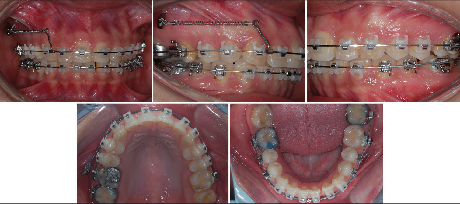
Treatment was carried out with self-ligating appliance, straight-wire technique, Roth prescription, slot 0.022-in (QuicKlear, Forestadent, Germany). Alignment and leveling were carried out with CuNiTi 0.014-in archwires, followed by CuNiTi 0.014-in × 0.025-in maxillary and mandibular archwires. Each pair was kept for 2 months [Figure 3].
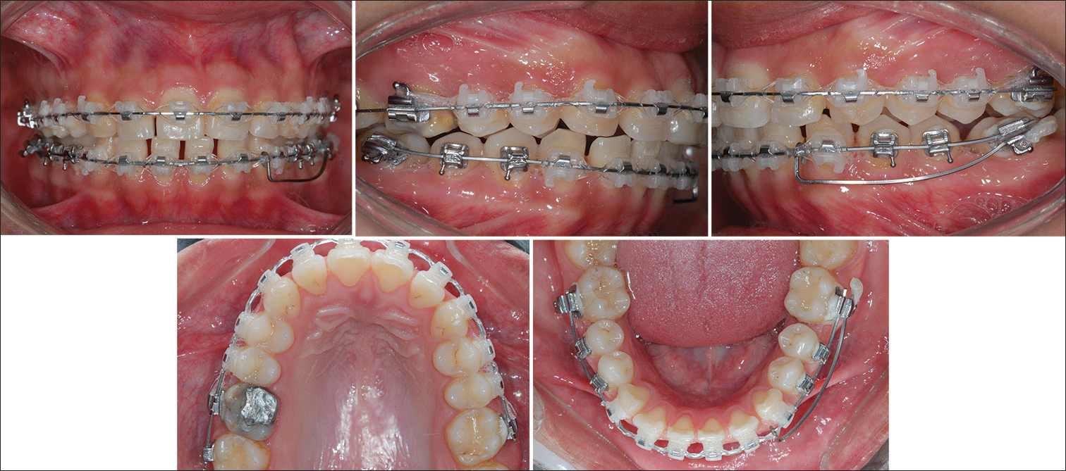
- Alignment and leveling carried out with CuNiTi 0.014-in archwires, followed by CuNiTi 0.014-in × 0.025-in maxillary and mandibular archwires. Each pair was kept for 2 months. By reason of mandibular second molar mesialization on the left side – necessary because of loss of first molar – it was decided for cantilever spring (TMA 0.017-in × 0.025-in) placement over the rectangular double molar tube, so as to produce a clockwise moment (tip-back) and upright the tooth. Force ranged from 50 to 60 g
By reason of mandibular second molar mesialization on the left side – necessary because of loss of first molar – it was decided for cantilever spring (TMA 0.017-in × 0.025-in) placement over the rectangular double molar tube, so as to produce a clockwise moment (tip-back) and upright the tooth [Figure 3]. Force exerted for the cantilever spring basically depends on measuring the moment to be produced over the molar to be uprighted. The moment of force necessary for molar uprighting usually ranges from 1500 gr/mm to 2000 gr/mm.[1] Moment is estimated by multiplying force by the distance covering the point of cantilever spring application (M = FxD), which goes from the molar tube to the canine mesial surface. In the clinical case reported herein, once the distance from molar to canine mesial surface (30 mm) and the moment of force to be produced for molar distalization (1500–2000 gr/mm) were known, it was possible to find the force to be exerted to activate the cantilever spring (50–60 g). Mandibular second molar uprighting on the left side lasted for 4 months. Figure 4 show the use of CuNiTi 0.017-in × 0.025-in archwires 8 months after treatment onset.
- Six months after treatment onset with CuNiTi 0.017-in × 0.025-in archwires. Note correction of molar mesioangulation. Mandibular second molar uprighting on the left side lasted for 4 months
Biomechanics of distalization with mini-screw placed in the infrazygomatic crest
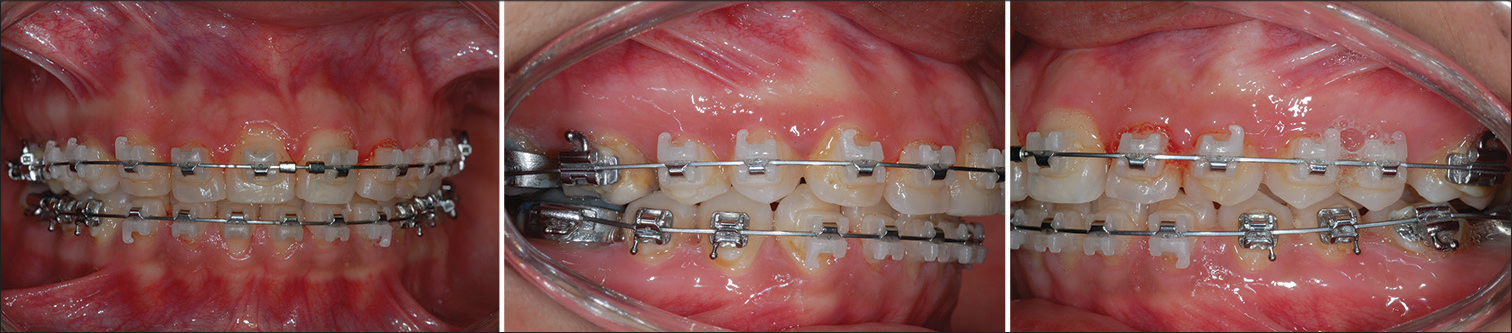
Figures 5 and 6 (7 months after treatment onset) reveal the start of distalization with unilateral mini-screw placement in the IZC area for anchorage during maxillary retraction and rotation. The IZC area is a portion of the cortical bone located at the zygomatic process of the maxilla. The latter is a bone protrusion evidently seen over the curvature between the alveolar process and maxillary zygomatic bone.[13] Young adults have this area located between second premolar and maxillary first molar, whereas adults have the area located near the first molar. A tomographic study[14] suggested fitting the screw into the IZC located over the maxillary first molar mesiobuccal root 14 mm to 26 mm above the maxillary occlusal plane and first molar, so as to form an insertion angle ranging from 55° to 70° relative to the maxillary occlusal plane. However, another study on the aforementioned mechanics[15] revealed the best portion of IZC area for screw placement must follow second molar mesiobuccal root spatial orientation. This is because the area has thicker, denser bone in comparison to the area around first molar. Therefore, it was decided for screw placement following maxillary second molar mesiobuccal root spatial orientation, as advocated by the aforementioned study.[15]
- The distalization system was composed of a steel 0.017-in × 0.025-in rectangular archwire to which a customized hook was secured with greater cervical extension, so as to not only allow force to be directed as near as possible the center of resistance (Cr) of all teeth on the same side but also produce a translatory movement. A 9-mm closed NiTi spring from the mini-screw to the hook previously secured to the infrazygomatic crest area was used. Force for maxillary retraction ranged from 280 to 340 g
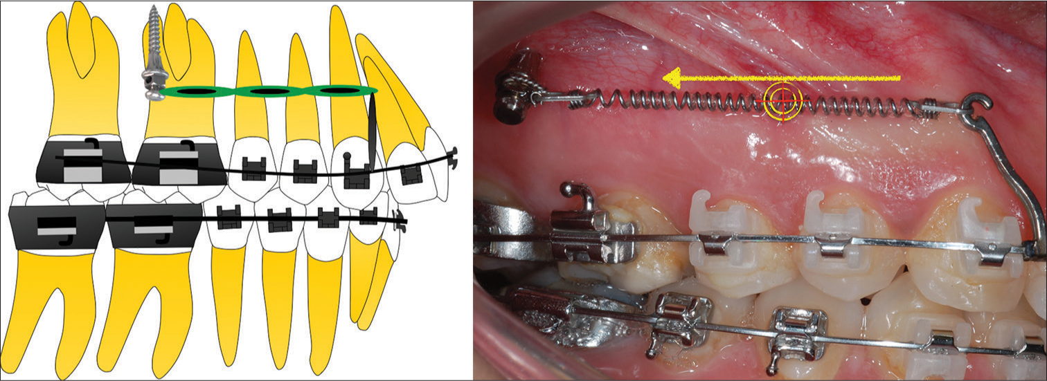
- Diagram illustrating the biomechanics employed during unilateral distalization 7 months after treatment onset. Note distalization with unilateral mini-screw (10 mm × 1.5 mm) placement (Morelli, Sorocaba, SP, Brazil) in the infrazygomatic crest area for anchorage during maxillary retraction and rotation
Figure 6 shows that the screw angulation is approximately equal to 70° relative to the maxillary occlusal plane. Initially, a spear tip (Morelli, Sorocaba, SP, Brazil) was used to guide MI placement [Figure 7], and a hexagonal driver was used for MI (10 mm × 1.5 mm, Morelli, Sorocaba, SP, Brazil) fitting [Figure 7]. Following screw placement, en masse distalization was carried out. The retraction system was composed of a steel 0.017-in × 0.025-in rectangular archwire to which a customized hook was secured with greater cervical extension, so as to not only allow force to be directed as near as possible the center of resistance (Cr) of all teeth on the same side but also produce a translatory movement [Figure 5]. A 9-mm closed NiTi spring from the mini-screw to the hook previously secured in the IZC area was used as shown in Figure 6. According to the literature, the ideal force for maxillary retraction must range from 280 to 340 g.[15] It is important to highlight that when it comes to this mini-screw mechanics in specific, the following three parameters are applied: (a) compulsory third molar extraction, (b) use of a higher screw for fitting in the IZC area, and (c) absent pneumatization of maxillary sinus in the area covering both maxillary second and first molar. Panoramic radiograph [Figure 2] reveals maxillary sinus has not been lowered down between first and second molar roots, which allows the screw to be placed in the area. The patient was advised to perform proper cleaning, once the screw was placed in a nonkeratinized area.
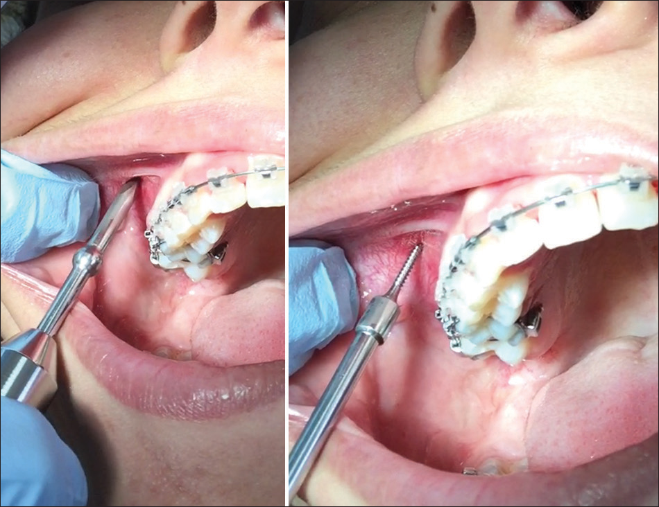
- Mini-implant placement met the following criteria: initially, a spear tip (Morelli, Sorocaba, SP, Brazil) was used as guide drill for mini-implant placement [Figure 7], and an hexagonal driver was used for mini-implant (10 mm × 1.5 mm, Morelli, Sorocaba, SP, Brazil) fitting. Screw angulation is approximately equal to 70° relative to the maxillary occlusal plane
Figure 8 show the finishing stage of treatment 17 months later, with braided steel 0.019-in × 0.025-in archwires. Satisfactory posterior relationship between molars and canines on the right side was evinced. In addition, the force exerted by the elastic toward the screw was redirected to the area of the right canine bracket. The mechanics was rendered necessary since the incisal plane was subjected to mild counterclockwise tipping, as seen in Figure 8. Thus, oblique elastic placement allows tipping to be corrected while aiding correction of remaining midline minor deviation. Class II elastics were placed on the right side for closure of a minor diastema opening in the mandible. Closure was achieved by means of molar mesialization.
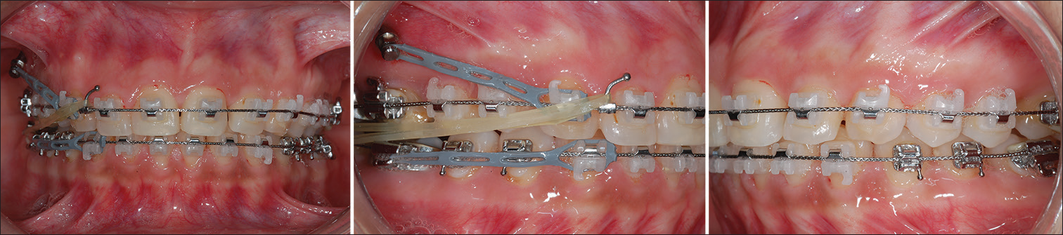
- Finishing stage of treatment 17 months later, with braided steel 0.019-in × 0.025-in archwires. Satisfactory posterior relationship between molars and canines on the right side was evinced. In addition, the force exerted by the elastic toward the screw was redirected to the area of the right canine bracket. The mechanics was rendered necessary since the incisal plane was subjected to mild anticlockwise tipping, as seen in Figure 8. Thus, oblique elastic placement allows tipping to be corrected while aiding correction of remaining midline minor deviation. Class II elastics were placed on the right side for closure of a minor diastema opening in the mandible. Closure was achieved by means of molar mesialization
Treatment outcomes
Figure 9 reveal the outcomes achieved after 20 months of treatment. Both frontal and lateral facial analyses reveal minor changes occurring from treatment start to finish, with little lip retraction resulting from maxillary incisors lingual tipping. Undoubtedly, smile analysis reveals enhanced smile arc (parallel) and upper dental midline coinciding with patient’s median plane. The most significant changes were regarding sagittal relationship established between molars and canines on the right side. Analysis of the cephalogram in lateral view revealed no skeletal changes resulting from the mechanics of choice. Table 2 evinces an unchanged skeletal maxillomandibular relationship, which proves that the most significant changes resulting from Class II treatment were of a dentoalveolar nature. Cephalometric analysis revealed maxillary and mandibular incisors underwent retraction relative to the basal bone and so did the soft profile (upper and lower lips). Mandibular incisors lingual tipping was expected since diastemata closure inevitably leads to some degree of retraction, as seen by cephalometric tracings superimposition [Figures 10 and 11]. It is worth highlighting that the patient underwent rhinoplasty during orthodontic treatment, which might have led to tissue changes, particularly regarding lips and correlated soft tissues. This might have slightly increased the nasolabial angle, thus, resulting in a more pleasant profile due to lip retraction associated with rhinoplasty.
Superimposition on the cranial base (sella–nasion) shown in Figure 11 indicates effects derived from mechanics, with minor dental effects and normal molar relationship. Figure 11 shows total superimposition of the maxilla and mandible, which reveals maxillary molar distalization, as well as little extrusion and lingual tipping of incisors. Lingual tipping of mandibular incisors was evinced by superimposition of the mandible.
- Final outcomes achieved after 20 months of treatment. Both frontal and lateral facial analyses reveal minor changes occurring from treatment start to finish, with little lip retraction resulting from maxillary incisors lingual tipping. Undoubtedly, smile analysis [Figure 9] reveals enhanced smile arc and upper dental midline coinciding with patient’s median sagittal plane. The most significant changes were regarding the sagittal relationship established between molars and canines on the right side
| Cephalometric variables | Values |
|---|---|
| SNA | 87° |
| SNB | 80° |
| ANB | 7° |
| Sn.GoMe | 37° |
| 1-NA | 0 mm |
| 1-SN | 96° |
| IMPA | 94° |
| 1-NB | 7 mm |
| Ls-E | −1.7 mm |
| Li-E | −1.3 mm |
- Panoramic radiograph and cephalogram in lateral view at treatment completion
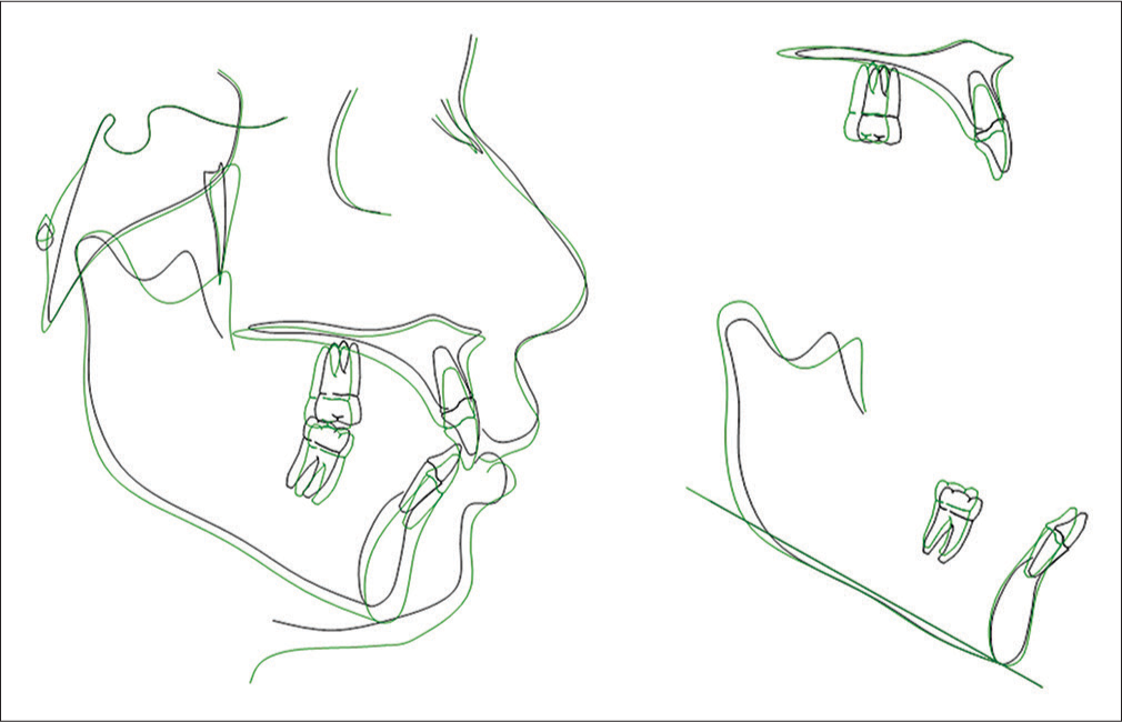
- Initial and final cephalometric tracings total superimposition on the sella–nasion line isolated in both the maxilla and mandible
Discussion
Cases of Class II subdivision with maxillary implications are often treated by means of maxillary first premolar extraction on the malocclusion side. With the advent of MIs, one of the most effective anchorage resources used to address anchorage loss is the asymmetric use of screws.[19] With a view to correcting asymmetric Class II without extraction, treatment seeks to produce distalization of maxillary teeth, particularly of molars. To do so, the methods of choice vary from the most conventional, such as headgear appliance,[4] to the most ingenious inventions regarding intraoral jig appliances.[1-3,10-12] The headgear appliance used to be widely employed to correct sagittal molar relationship; however, it is hardly accepted by patients nowadays. Hence, a number of appliances and methods of intraoral molar distalization have arisen with a view to requiring less patient’s compliance, namely, NiTi springs, magnetic appliances, Jones Jig appliance, Pendulum appliance or Pendex, Distal Jet appliance, and among others. However, recurring undesirable side effects are produced, namely, uncontrolled molar tipping and anchorage loss of supporting teeth.
The use of MIs for molar distalization in modern orthodontic practice has become an important tool for orthodontists.[20-23] Undoubtedly, skeletal anchorage with mini-screws, used for molar distalization, minimize undesirable side effects, especially in comparison to conventional anchorage appliances. Nevertheless, the most significant problem of distalization carried out with the aid of MIs placed in the alveolar region, that is, between roots, is that distal movement of teeth is limited since the screw prevents premolars from undergoing distalization without reinserting the screw at another inter-root site. Molar distalization is usually carried out at two stages. At stage one, distalization of first and second molars is achieved with the aid of a mini-screw-anchored cursor, with molars distally moved, as desired. Subsequently, screws are reinserted at a different site for retraction of premolars and anterior teeth.
The literature has recommended the use of anchorage mini-plates for complete distalization of the maxilla.[24] The authors have found molar distalization at around 3.78 mm in the region of crowns and 3.20 mm in the region of roots and concluded the use of a skeletal anchorage system (SAS) combined with mini-plates is recommended for Class II correction by means of maxillary distalization. No studies quantifying the degree of distalization achieved with the aid of mini-screws placed in the IZC have been found in the literature. However, preliminary outcomes achieved by clinical cases are rather optimistic. Furthermore, because there is no need for mucosa opening surgical procedures aimed at placement and removal of mini-plates, the mini-screw method becomes more advantageous and costs are reduced.
The use of higher mini-screws (10 mm) placed at sites other than root areas, as it is the case of the IZC, allows more versatility of orthodontic movement since tooth roots do not interfere in tooth displacement. As a result, the maxilla undergoes distalization as a whole. In the present clinical case, it was decided for a higher screw (10 mm) with a 1.5-mm diameter (Morelli, Sorocaba, SP, Brazil). Mini-screw placement usually follows the attached gingiva. Placement near the free gingiva (mucosa) is avoided. Higher MIs (>10 mm) should be preferred in cases of MI placement at the IZC which, whenever possible, should be carried out near the mucogingival line. The present clinical case had screw placement carried out in the mucosal area. This is because patient’s attached gingiva was rather constricted, which could cause the screw head to touch the second molar tube and, as a result, prevent distalization from being achieved on this side. The major issue concerning screw placement at free gingival sites is that chances of failure increase significantly, particularly because this area is more likely to be affected by local inflammation and plaque buildup. Some authors[25] have found low success rates regarding MIs placed in the IZC area or the buccal mucosal surface (46% after 1 year).
A recent study[18] assessed unsuccessful outcomes regarding screw placement in the IZC. A total of 30 patients previously subjected to MI mechanics in the IZC (55 screws) were analyzed. MIs with height ranging from 6 mm to 9 mm and diameter ranging from 1.5 mm to 2.3 mm were placed with an angle ranging from 40° to 70° near first molars and, in most cases, at free gingival sites. The authors found failure rates in 21.8% of cases. The aforementioned value is greater than that showed by a recently published systematic review[26] (14% failure rate). The study assessed MIs fitted at inter-root sites. Nevertheless, a different study[13] found a success rate of 100% for MIs placed in the IZC. It is worth highlighting that the authors used screws that were 17-mm tall. The first study[18] attempted to establish a relationship among factors that most likely lead to failure. The following were mentioned as potential causes: insufficient hygiene; age; sex; MI type, height, and diameter; traction force; type of movement; clinician’s experience; previous guided drill; and stress distribution on placement side (right or left). The authors concluded that none of those factors have been associated with higher or lower failure rates regarding MI mechanics in the IZC. However, they highlighted that higher MIs fitted into attached gingiva might decrease the potential for local inflammation at the site. In the present clinical case, the MI lasted for 10 months as anchorage for distalization without any need for removal. A different study[27] states an extremely low probability of MI penetrating the maxillary sinus when placed in the IZC. Nevertheless, it must be highlighted that the author recommends 12 mm × 2 mm screws be used. That is, screws that are slightly higher than that used (10 mm × 1.5 mm) in the present study. Therefore, screw placement at sites other than the socket, especially in the IZC area, as it is the case of the present study, has become popular among orthodontists. This is because the technique is more likely to allow greater sagittal movement resulting from maxillary distalization, without any interference of tooth roots. Thus, it is considered a rather simpler and more effective method in comparison to the use of skeletal anchorage mini-plates.
Conclusion
Asymmetric malocclusion in adult patients has always represented a challenge to orthodontists, especially Class II subdivision with maxillary implications. A number of protocols are recommended for treatment, namely, asymmetric extraction or unilateral molar distalization. The latter, carried out with the aid of MIs used for anchorage, is a clinical reality for orthodontists. Mini-screw placement in the IZC area (IZC) has been advocated in the literature, as it allows more biomechanical versatility of orthodontic movement since high screws prevent tooth roots from interfering in tooth displacement. Therefore, MIs free clinicians from the need for patient’s compliance and increase the amount of treatment options, thus providing ease to cases initially seen as too complex or unfeasible in terms of conventional orthodontic treatment methods.[28] We conclude that biomechanics of unilateral molar distalization combined with skeletal anchorage at other sites, but the socket has allowed predictable outcomes to be achieved with minimal need for patient’s compliance and minor side effects. In addition, it is considered a rather simpler method in comparison to mini-plates.
Declaration of patient consent
The authors certify that they have obtained all appropriate patient consent forms. In the form the patient(s) has/have given his/her/their consent for his/her/their images and other clinical information to be reported in the journal. The patients understand that their names and initials will not be published and due efforts will be made to conceal their identity, but anonymity cannot be guaranteed.
Financial support and sponsorship
Nil.
Conflicts of interest
There are no conflicts of interest.
References
- Application of biomechanics in the correction of Orthodontic asymmetries In: Clinical Orthodontics and biomechanics. Maringá, PR: Dental Press; 2010. p. :243-300. Ch. 8
- [Google Scholar]
- Application of biomechanics in the correction of dental asymmetries. Rev Clín Ortod Dent Press. 2008;7:92-8.
- [Google Scholar]
- Treatment strategies for midline discrepancies. Semin Orthod. 1996;2:84-9.
- [CrossRef] [Google Scholar]
- Treatment of Class II subdivision malocclusion with asymmetrical molar distalization. Rev Clín Ortod Dent Press. 2013;12:50-62.
- [CrossRef] [Google Scholar]
- Prevalence and etiology of asymmetries in occlusion. Angle Orthod. 1979;49:199-204.
- [CrossRef] [Google Scholar]
- Skeletal and dental asymmetries in class II subdivision malocclusions using cone-beam computed tomography. Am J Orthod Dentofacial Orthop. 2010;138(542):e1-20.
- [CrossRef] [PubMed] [Google Scholar]
- Facial esthetics in relation to orthodontic treatment. Angle Orthod. 1952;22:3-22.
- [CrossRef] [Google Scholar]
- Pitch, roll, and yaw: Describing the spatial orientation of dentofacial traits. Am J Orthod Dentofacial Orthop. 2007;131:305-10.
- [Google Scholar]
- Rapid class II molar correction with an open-coil jig. J Clin Orthod. 1992;26:661-4.
- [CrossRef] [Google Scholar]
- Class II subdivision treatment with tip-back moments. Eur J Orthod. 1997;19:93-101.
- [CrossRef] [PubMed] [Google Scholar]
- Upper molar distalization: A critical analysis. Orthod Craniofac Res. 2002;5:114-26.
- [Google Scholar]
- Do miniscrews remain stationary under orthodontic forces? Am J Orthod Dentofacial Orthop. 2004;126:42-7.
- [Google Scholar]
- A computed tomographic image study on the thickness of the infrazygomatic crest of the maxilla and its clinical implications for miniscrew insertion. Am J Orthod Dentofacial Orthop. 2007;131:352-6.
- [Google Scholar]
- Mini-screw or Mini-plate, which is better for whole upper arch distalization. News Trends Orthod. 2007;1:1-2.
- [Google Scholar]
- Severe anterior open-bite case treated using titanium screw anchorage. Angle Orthod. 2004;74:558-67.
- [Google Scholar]
- Appliances, mechanics, and treatment strategies toward orthognathic-like treatment results In: Nanda R, ed. Temporary Anchorage in Orthodontics. St. Louis: Mosby; 2009.
- [Google Scholar]
- Failure rates of mini-implants placed in the infrazygomatic region. Prog Orthod. 2015;16:31.
- [Google Scholar]
- Class II subdivision malocclusion treated with unilateral extraction and temporary anchorage (mini-implants): Case report. Rev Clín Ortod Dent Press. 2013;12:78-85.
- [Google Scholar]
- Correction of class II deep overbite and dental and skeletal asymmetry with 2 types of palatal miniscrews. Am J Orthod Dentofacial Orthop. 2007;131:S106-16.
- [CrossRef] [PubMed] [Google Scholar]
- Group distal movement of teeth using microscrew implant anchorage. Angle Orthod. 2004;75:510-17.
- [Google Scholar]
- Molar distalization using orthodontic titanium mini-implants. Rev Clín Ortod Dent Press. 2008;7:40-5.
- [Google Scholar]
- The use of intermaxillary elastics and molar distalization with mini-screws in the correction of Class II malocclusion with self-ligating appliances: Case reports. Rev Clín Ortod Dent Press. 2014;13:41-58.
- [Google Scholar]
- Distal movement of maxillary molars in nongrowing patients with the skeletal anchorage system. Am J Orthod Dentofacial Orthop. 2006;129:723-33.
- [Google Scholar]
- Survival analyses of surgical miniscrews as orthodontic anchorage. Am J Orthod Dentofacial Orthop. 2009;136:29-36.
- [CrossRef] [PubMed] [Google Scholar]
- Failure rates and associated risk factors of orthodontic miniscrew implants: A meta-analysis. Am J Orthod Dentofacial Orthop. 2012;142:577-95.e7.
- [Google Scholar]
- A new method of placing orthodontic bone screws in IZC. News Trends Orthod. 2009;1:4-7.
- [Google Scholar]