Translate this page into:
Modified Precision Lingual Bonding Technique: A Step-wise Approach with Torque Angulation Device-bracket Positioning Device
This article was originally published by Wolters Kluwer and was migrated to Scientific Scholar after the change of Publisher.
Abstract
Objectives
Contemporary preadjusted edgewise appliance is all about the precision in bracket design, prescription and positioning in addition to the orthodontist’s skill and training. However, achieving it is a bigger challenge as the anatomy of the lingual surface of a tooth is uneven, dissimilar, and moreover the tooth alignment on the lingual surface is variant. Thus, the need for an accurate method of bracket positioning with predetermined torque and angulation incorporated in the brackets according to the patients’ need is of key importance.
Materials and Methods
A TAD- BPD machine used to enhance the accuracy of bracket positioning and bioplast accurate tray transfer technique was used.
Results
A step-wise procedures in bracket positioning and fabricating an indirect bonding tray for lingual orthodontics using the torque angulation device-bracket positioning device.
Conclusions
This technique facilitated unhindered bonding even in severely crowded cases and easy rebonding during mid-treatment stages.
Keywords
Indirect bonding
lingual orthodontics
torque angulation device-bracket positioning device

Introduction
“Necessity is the mother of invention.” So was the invention of the lingual orthodontic technique in 1980 by Kurz,[1] California, and Fujita,[2] Japan, whose clientele was dominated by renowned personalities.
As in contemporary preadjusted edgewise labial orthodontic appliance, the greatest challenge in the success of lingual orthodontic therapy depends undoubtedly on the perfection in bracket design, prescription, and its positioning in addition to the orthodontist’s skill and training.
The reason being the anatomy of the lingual surface of a tooth is uneven, dissimilar, and moreover the tooth alignment on the lingual surface is variant. Thus, the need for an accurate method of bracket positioning with predetermined torque and angulation incorporated in the brackets according to the patients’ need is of key importance.[3]
There are various methods of bracket positioning as follows:
The lingual bracket jig by Dr. Silvia Geron in 1982 was a method in which lingual brackets were bonded directly[4]
In 1984, the Ormco Company devised the torque angulation reference guide (TARG) machine which incorporated the necessary torque and angulation required but had a wooden base which impeded precision during bonding[5]
In 1986, the customized lingual appliance setup service system was introduced with the idea of dealing better with the anatomic discrepancies of the lingual surfaces of the teeth. This was accomplished by constructing an ideal diagnostic setup from a duplicate setup model of the patient’s original malocclusion[6]
In 1987, Fillion introduced the BEST system in which the second-order bends in the anterior section were eliminated, but the bends in the premolar and molar regions were not avoided[7]
In 1996, HIRO system used the ideal arch form with 0.018” × 0.025” stainless steel wire to position the brackets on the setup. In this, they used single tooth transfer trays[8]
In 1997, the Transfer Optimized Positioning System was devised by a German professional Dr. Weichmann. Later, he invented the CAD/CAM Incognito system with its customized gold brackets[9]
In 2004, a real breakthrough in lingual orthodontics occurred with the invention of the torque angulation device (TAD)[10]
In 2006, the first TAD with digital TARG accurate to 0.1° was invented. Along with this, a bracket positioning device (BPD) was devised to facilitate easy bracket placement.[10]
In this article, the step-wise procedure in bracket positioning and fabricating an indirect bonding tray for lingual orthodontics is detailed using the TAD-BPD.
Armamentarium
TAD: It consists of a fine adjustment screw, locking screw, liquid crystal display (LCD), angulation fine adjustment knob, torque arc movement assay, and torque fine adjustment knob [Figure 1].
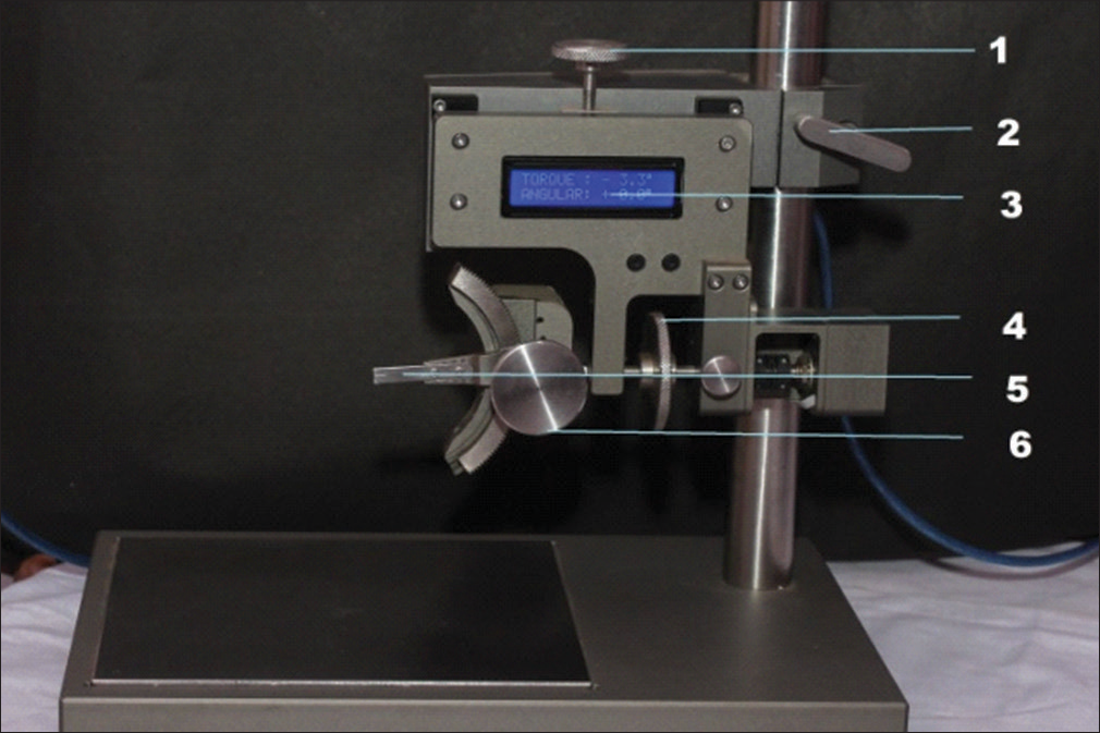
- Torque angulation device
BPD: It consists of a fine adjustment screw, locking screw, LCD, a caliper, and a bracket attachment jaw [Figure 2].
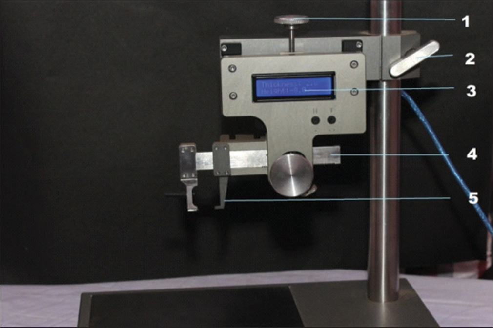
- Bracket positioning device
In addition, there are a cast surveyor [Figure 3]; height- measuring gauge, hand instruments, adhesive and lingual brackets [Figure 4].
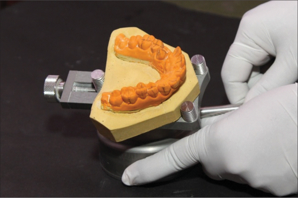
- Cast surveyor

- Height-measuring gauge, hand instruments, adhesive and lingual brackets
Steps Involved in Indirect Bracket Positioning and Transfer Tray Fabrication
Step I: Preparing the casts
Working models are trimmed appropriately so that they could be easily mounted on the cast surveying base [Figure 5]
 Figure 5
- Trimmed models with bases
Long axis of the clinical crown is marked on the labial and lingual surfaces of the tooth [Figure 6a and b]
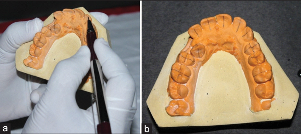 Figure 6
- (a and b) Marking the long axis of the clinical crown on the labial and lingual surfaces of the tooth
The midpoint of the clinical crown is also marked with a measuring gauge [Figure 7a and b]
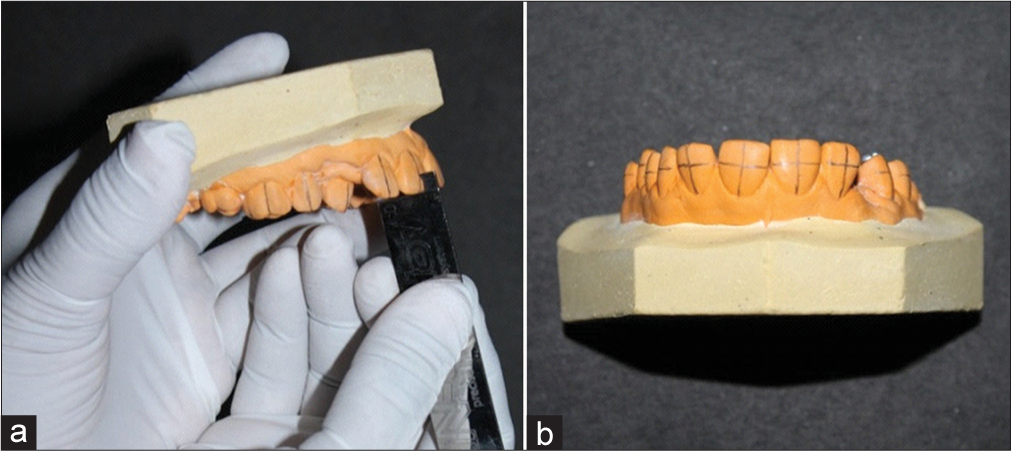 Figure 7
- (a and b) Midpoint of the clinical crown is marked with the help of the measuring gauge, and the horizontal orientation lines are marked
Horizontal orientation lines corresponding to the midpoint of the clinical crown are marked to get an intersecting point on the labial surface of the crown
Once the models are ready, they are sectioned into three different parts using a die cutter. This procedure is done so that the lingual bonding could be accomplished unhindered [Figure 8a and b].
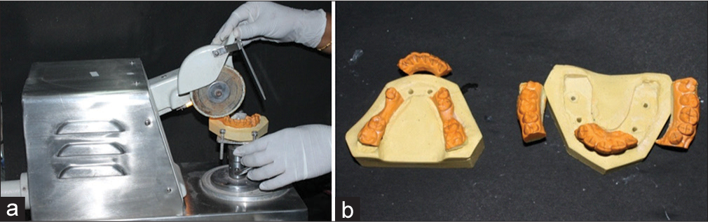 Figure 8
- (a and b) The models are sectioned into three different parts using a die cutter
Step II: Setting the model according to the desired angulation and torque using the torque angulation device
Before setting the machine to the desired torque and angulation, the accuracy of the TAD is verified using the orientation guide [Figure 9]
 Figure 9
- Verifying the accuracy of the torque angulation device using the orientation guide
Torque fine adjustment knob is set to the desired torque value [Figure 10]
 Figure 10
- Adjusting the torque to the desired value
Angulation fine adjustment knob is set to the desired angulation value [Figure 11]
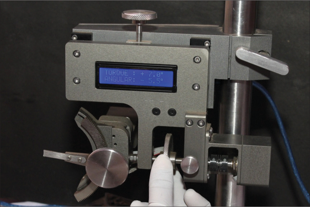 Figure 11
- Adjusting the angulation to the desired value
The models with the orientation lines are mounted on the cast survey base. They are adjusted such that the center of the torque arc movement assay corresponds to the intersecting lines on the labial surface of the model. Once the position of the model is verified three dimensionally, the models are fixed on the model survey base by closing the knob [Figure 12].
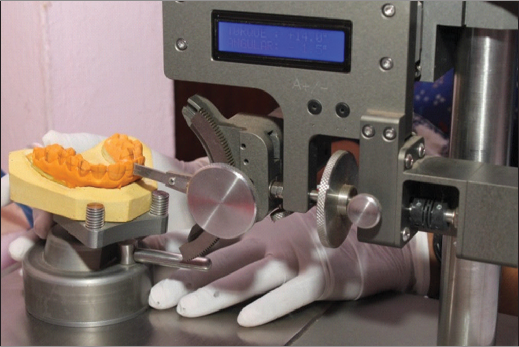 Figure 12
- Adjusting the cast on the cast surveying base so that the center of the torque arc movement assay coincides with the intersection of the vertical and horizontal orientation lines
Step III: Positioning the bracket using the bracket positioning device and curing the adhesive
The bracket attachment jaws are adjusted to an initial height and thickness corresponding to 0 (zero). After surveying the model, the desired height and thickness are formulated and a chart is prepared. With this preparations, the model is ready for the bonding procedure [Figure 13]
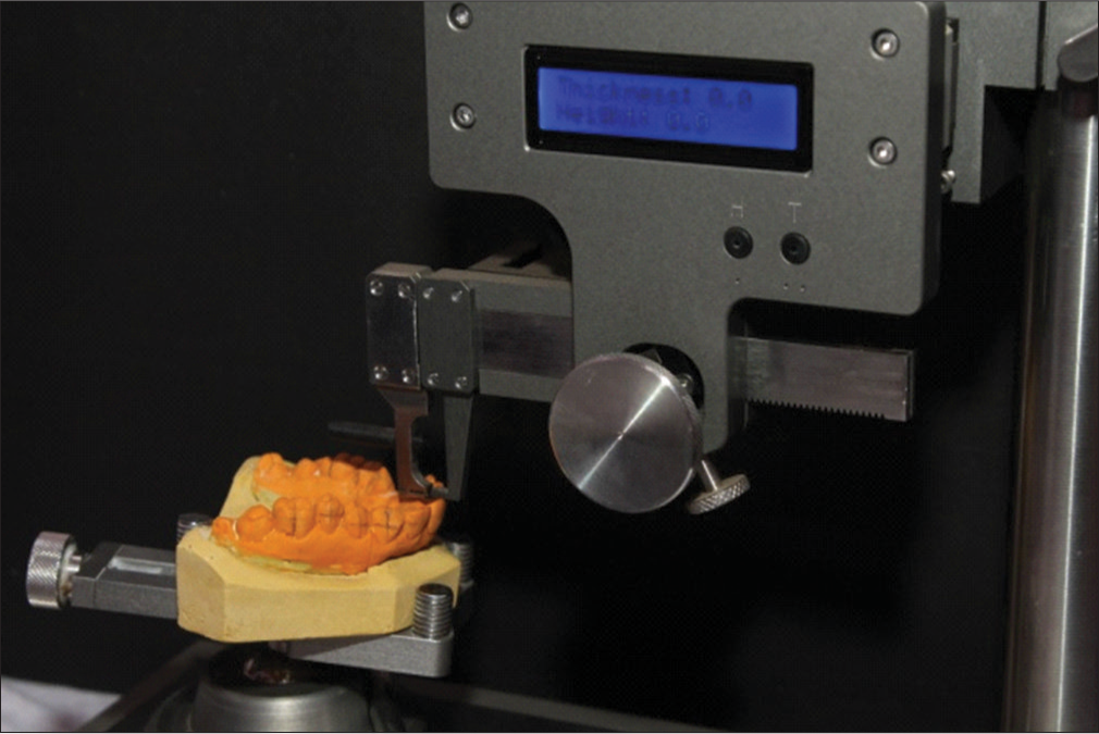 Figure 13
- The bracket attachment jaw is corrected to a height and thickness of 0 initially
Bracket is fixed on one of the bracket adjustment jaws. Primer is applied on the bracket base followed by placing sufficient amount of adhesive
The bracket attachment jaw is adjusted to the predetermined height and thickness according to the formulated chart. Once again the position of the bracket is verified three dimensionally and the adhesive is cured [Figure 14, 15a, b, 16a and b]
 Figure 14
- Chart prepared after surveying the model
 Figure 15
- (a and b) Applying the primer and adhesive onto the bracket base
 Figure 16
- (a and b) Excess composite is smoothened and light cured after confirming the bracket position three dimensionally
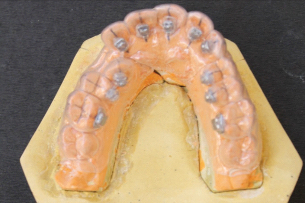
Similarly, the rest of the brackets are placed on the teeth according to the chart prepared [Figure 17a and b].
 Figure 17
- (a and b) Completed bonding according to the prepared chart
Step IV: Preparation of the transfer trays

Discussion
Considering the variations in lingual crown morphology and the slope of the maxillary anterior teeth,[11] any small variation in bracket height could affect the torque delivered to the tooth much more than with labial appliance. Kyung used a Mushroom bracket positioner to determine the most suitable height for bracket positioning.[3] In our method of bonding, the individual tooth was surveyed initially and a chart was prepared according to the particular case using the TAD/BPD. Moreover, to ensure the most accurate unhindered bracket position on the lingual surface, we used a cast which was precisely cut into three sections using a model die cutter. Care was taken so that the morphology of the lingual surface of the teeth was preserved. Previously, for bonding severely rotated tooth, duplication of models was mandatory. By following this technique, duplication of models was avoided by bonding onto a rotated tooth by detaching the hindering portion on the model easily.
Although DAS occlusal window addition silicon putty transfer tray system offered easy removal of occlusal and incisal flash removal, it lacked rigidity for individual tooth bracket transfer which was required in the cases of progressive bonding or rebonding of debonded brackets.[12] So far, most of the authors prefer Hiro’s transfer tray technique[13] and Kommon base technique[14] for rebonding procedure. We used transfer trays made of 1 mm thickness vacuum-formed soft sheets. This facilitated easy removal of the sheet after completion of the bonding procedure. Moreover, rebonding was also very easy as the individual tooth on the tray could be easily cut using a scissors and the rebonding could be done even during the mistreatment when the adjacent tooth changed positions.
Conclusion
The main advantage in this method of lingual bonding is the die cutting procedure which facilitated unhindered bonding even in severely crowded tooth. Duplication of models was not required. Placing the composite material beneath the bracket delivered the exact amount of torque required. The use of soft vacuum form trays not only facilitated precise bonding, but also removal of the trays after bonding procedure was also easy. This type of transfer tray facilitated easy rebonding even during mid treatment time. Thus, the secret behind a beautiful smile in lingual orthodontics to a great extent depends on the precise handwork in the laboratory procedure.
Financial support and sponsorship
Nil.
Conflicts of interest
There are no conflicts of interest.
References
- Lingual orthodontics: A status report. Part 2: Research and development. J Clin Orthod. 1982;16:735-40.
- [Google Scholar]
- New orthodontic treatment with lingual bracket mushroom arch wire appliance. Am J Orthod. 1979;76:657-75.
- [CrossRef] [Google Scholar]
- The lingual plain-wire system with micro-implant anchorage. J Clin Orthod. 2004;38:388-95.
- [Google Scholar]
- Clinical advantages of the Orapix-straight wire lingual technique. Int Orthod. 2010;8:125-51.
- [Google Scholar]
- The customized lingual set-up service system In: Romano R, ed. Lingual Orthodontics. London: B. C. Decker, Hamilton; 1998. p. :63-173.
- [CrossRef] [Google Scholar]
- The thickness measurement system with the dali program In: Romano R, ed. Lingual Orthodontics. London: B. C. Decker, Hamilton; 1998. p. :63-173.
- [CrossRef] [Google Scholar]
- Resin core indirect bonding system-improvement of lingual orthodontic treatment. J Jpn Orthod Soc. 1998;57:83-91.
- [CrossRef] [Google Scholar]
- Lingual orthodontics (part 1): Laboratory procedure. J Orofac Orthop. 1999;60:371-9.
- [CrossRef] [PubMed] [Google Scholar]
- DAS’s incisal and occlusal window transfer tray for indirect bonding in lingual orthodontics. APOS Trends Orthod. 2013;3:62-6.
- [CrossRef] [Google Scholar]
- Indirect bonding technique in lingual orthodontics: The HIRO system. Prog Orthod. 2008;9:34-45.
- [Google Scholar]
- KommonBase for precise direct bonding of lingual orthodontic brackets. Int Orthod. 2010;8:14-27.
- [Google Scholar]